---
title: Posts tagged Harde waren
canonical: https://0110.be/tags/Harde%20waren
markdown_url: https://0110.be/tags/Harde%20waren.md
page: 0
posts_per_page: 30
total_posts: 9
filters:
tag: Harde waren
previous:
next:
---
# Posts tagged Harde waren
## [☀️ Solar sockets - Delivers power only on solar energy surplus](https://0110.be/posts/%E2%98%80%EF%B8%8F_Solar_sockets_-_Delivers_power_only_on_solar_energy_surplus.md)
- Published: 2023-08-23T00:00:00Z
- Updated: 2023-09-01T12:14:47Z
- Author: Joren
- ID: 516
- Canonical: https://0110.be/posts/%E2%98%80%EF%B8%8F_Solar_sockets_-_Delivers_power_only_on_solar_energy_surplus
- Tags: [0110.be](https://0110.be/tags/0110.be.md), [Harde waren](https://0110.be/tags/Harde%20waren.md), [UGent](https://0110.be/tags/UGent.md)
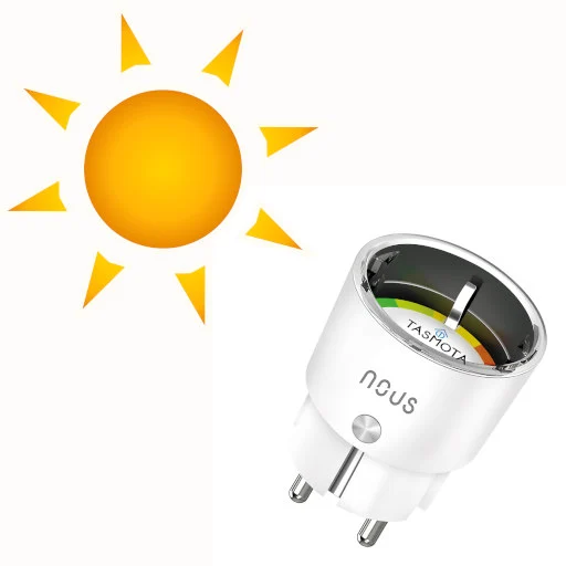
Fig: Solar socket.
I recently installed a couple of smart electrical sockets. The sockets only switch on *when there is a solar energy surplus*: when my rooftop solar panels produce more than the current energy consumption. I use these 'solar sockets' to charge the battery of an electric bike, for air conditioning and for charging other smaller devices. This post describes the components needed for such a system with the aim to inspire similar build.
1. Solar panels and a solar inverter with some form of readout.
2. A device to measure electrical energy use in a home.
3. Smart sockets with an easy to use API.
4. Some software to glue everything together.
### 1. ☀️ Solar panels and inverter
Most solar inverters have some form of API to readout the current solar panel output. In my case I use a SMA inverter which has two ways to extract this data: via Bluetooth and via wired ethernet. I found the wired ethernet solution to be the most reliable. The SMA inverter does use a somewhat annoying data formatting protocol but luckily there is an open source solution to decode the data: [SBFspot](https://github.com/SBFspot/SBFspot)
For SMA inverters, and possibly for others as well, there another option: the data is also automatically uploaded to a cloud based platform. This platform has an API which can be used to extract data on solar energy production. I do not like to be dependent on external cloud based software platforms, which might change at any time. Additionally, for real-time data cloud based platforms can be slow.
### 2. Measuring total electrical energy use
To measure total power use, I use an "Eastron SDM220M" measurement device which communicates with a server over a serial connection. There are adapters to translate serial Modbus to USB. The device is installed in my wiring closet by a professional: it is directly connected to the 60A mains and I would not advise to DIY it.
Alternatively, some places are equipped digital energy meters which might have a way for direct readout or readout via a cloud based API, after a few minutes. This might suffice for a solar socket install.
Energy use measurement might not be strictly needed for the 'solar sockets': if energy use is predictable it might be ok to simply switch the sockets on your average peak solar power. Perhaps combined with a local weather API. Finally we need to switch on some sockets.
### 3. Smart WiFi Socket
There are many smart WiFi sockets on the market. Most come with a smartphone app which allows you to control the socket from anywhere. Behind the scenes the sockets communicates with the vendor's cloud based system over the internet. Additionally there are some integrations with systems like Apple Home, Amazon Alexa en Google Assistant. For fundamental\
infrastructure like sockets in my home I want to avoid dependencies on a external cloud based systems. Next to the concerns about privacy and ownership there is a very practical concern: the cloud based system might just stop working in a few years. Especially [any dependency on a Google service](https://killedbygoogle.com/) is suspect. Also I am not convinced of [Amazon Alexa's](https://arstechnica.com/gadgets/2022/11/amazon-alexa-is-a-colossal-failure-on-pace-to-lose-10-billion-this-year/) future.
Luckily, there is *Tasmota* which provides open source firmware targeting many types of 'smart' devices including smart sockets. The tagline for Tasmota is *'Total local control with quick setup and updates'*. I bought a couple of [Nous A1T Tasmota Smart WiFi sockets](https://nous.technology/product/a1t4.html) which come with Tasmota firmware. Switching the socket on is done by sending an `HTTP GET` request to an url, which can be scripted easily. There is some
### 4. Control software
A script glues everything together: it logs energy usage and solar output. It switches on the solar sockets when a surplus is detected and switches again when the surplus is gone. There is some additional logic which ensures that the socket remains on for at least an hour even if there is no solar surplus. This to ensure that batteries are charged to a minimal usable state.
In summary, here we presented a couple of building blocks to build 'solar sockets' which are on only when there is a energy surplus. By using simple API's offered by Tasmota and locally running software, there is no dependency on (in the long term) unreliable cloud based systems which ensures the longevity of the build.
As an additional bonus, the solar sockets also serve as an indicator. A small LED shows when they are on, or, in other words, when there is solar energy surplus and when it is a good idea to switch on other electrical appliances.
---
## [USB MIDI interface for the NeXTCube - ISPW board](https://0110.be/posts/USB_MIDI_interface_for_the_NeXTCube_-_ISPW_board.md)
- Published: 2023-05-05T00:00:00Z
- Updated: 2025-11-29T14:18:42Z
- Author: Joren
- ID: 514
- Canonical: https://0110.be/posts/USB_MIDI_interface_for_the_NeXTCube_-_ISPW_board
- Tags: [Code](https://0110.be/tags/Code.md), [Harde waren](https://0110.be/tags/Harde%20waren.md), [Muziek](https://0110.be/tags/Muziek.md), [UGent](https://0110.be/tags/UGent.md)
I have recently [restored a NeXTCube with an ISPW Ariel soundcard](https://0110.be/posts/Electronic_Music_and_the_NeXTcube_-_Running_MAX_on_the_IRCAM_Musical_Workstation) with the aim to put it in the hands of artists and researchers in the context of a [living electronic music instrument heritage project](https://asil.ugent.be/projects/#heritageinstruments). To make the cube talk to keyboards, synths or other audio workstations I have built a *MIDI interface for the NeXTcube*.
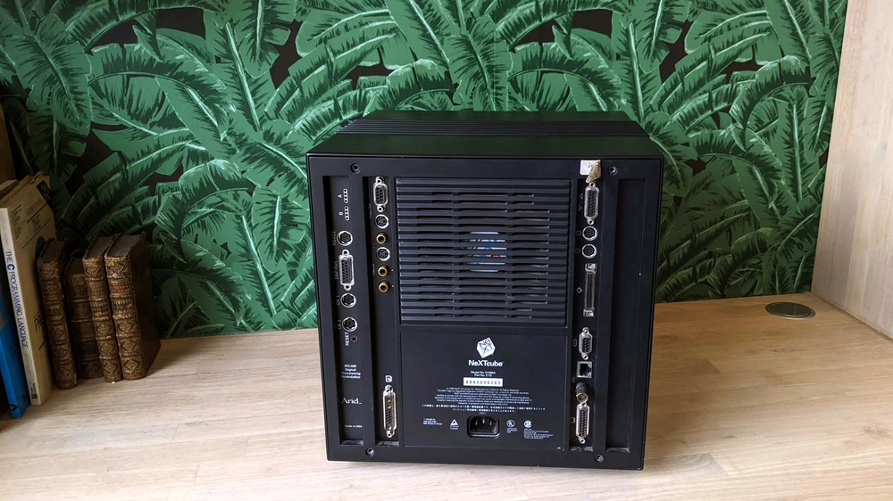
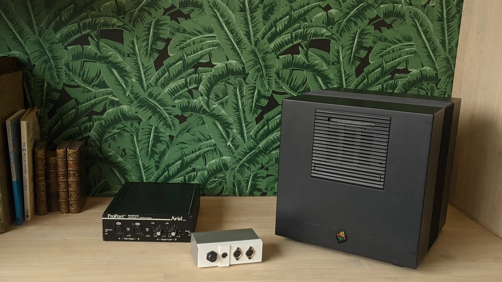
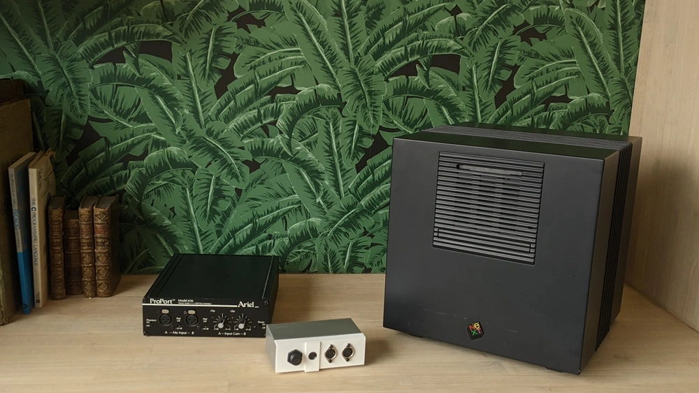
Fig: the NeXTCube with the Ariel ProPort and MIDI input/output interface.
Recently, I was able to restore a NeXTCube and install an early version of MAX - a graphical music programming environment. However, a crucial part of the system was missing: there was no way to do [MIDI input/output](https://en.wikipedia.org/wiki/MIDI). MIDI is used to connect controllers, keyboards, synthesizers or other musical instruments to the audio workstation. The NeXTCube itself has [a serial port which allows users to connect MIDI devices](https://www.nextcomputers.org/NeXTfiles/Docs/connectivity.pdf). Next to the serial port on the mainboard, the NeXTCube I am working with also has a RS-422 serial port on the ISPW 'soundcard'. The serial port uses RS-422 and mini DIN 8 connectors which provide MIDI input and output. While the MIDI data bytes are transmitted according to spec, the *connector and the electrical signals are not compatible with standard MIDI*.
Fig: the IRCAM/Ariel ISPW soundcard with mini DIN-8 RS-433 serial port on the right.
For MIDI I/O we need a device which allows to connect the RS-422 MIDI to both legacy MIDI devices and to computers via USB MIDI. If a MIDI event arrives from the NeXTCube's RS-422 it needs to be passed through to the USB and legacy MIDI ports and the other way around. The [Teensy platform](https://www.pjrc.com/teensy/) is ideal: it supports hardware serial and USB MIDI. In this retro-computing project, it seems wasteful to use the 600MHz Teensy 4.0 only for message passing: the Teensy has much more computing power than NeXTcube but it is cheap, easy to program, available and practical.
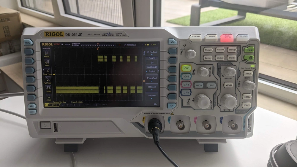
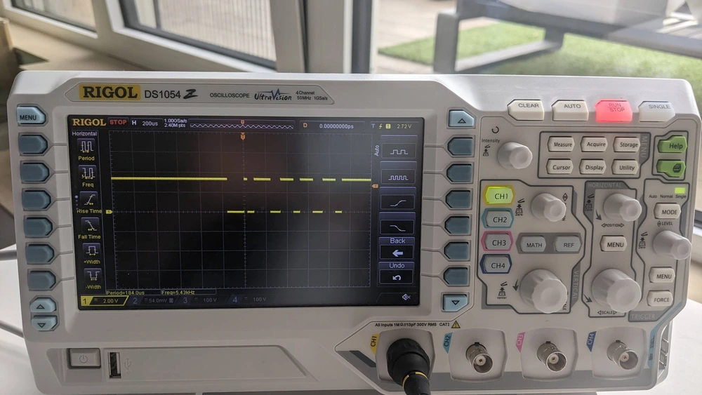
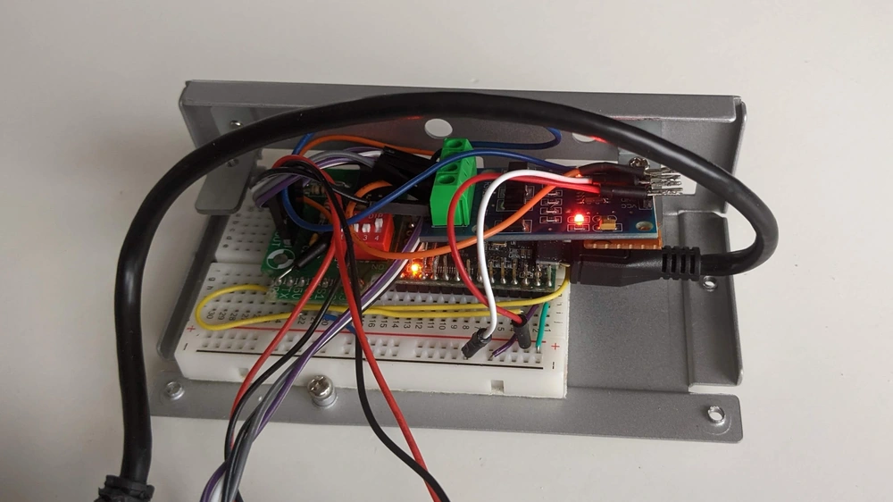
The RS-422 serial port uses --6V to 6V logic which needs to be transformed to the 0V to 3.3V logic for the Teensy microcontroller. A PCB provides this capability and is connected to a hardware serial port of the Teensy. The pinout of the RS-422 port was measured via a scope and matched the [documentation](https://allpinouts.org/pinouts/connectors/serial/apple-macintosh-rs-422-serial/). The Teensy has an `usbMIDI` mode and can present itself as a standard MIDI device to a PC. Two [opto-isolated legacy MIDI DIN-5 ports](https://www.sparkfun.com/products/12898) were connected to another hardware serial port. The software on the Teensy conducts the "three-way MIDI message passing":\[midi_passthrough.ino\].
Vid: Max/FTS FM synth reacting to USB MIDI input.
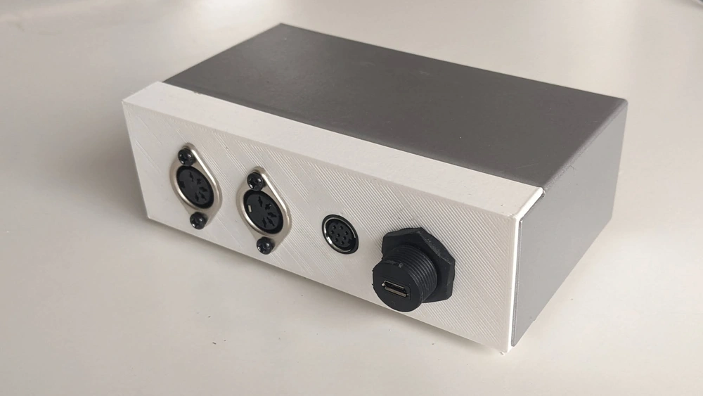
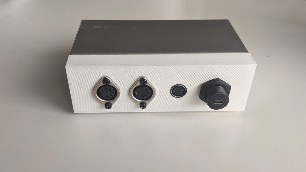
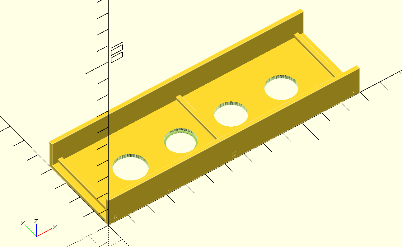
The electronics were fixed into a reused metal enclosure. The front panel of the enclosure was replaced by a custom 3D printed panel. The front contains the RS-422 port, two MIDI DIN 5 ports and a micro usb port either for power alone or MIDI messages and power. Feel free to check out the "OpenSCAD design with a level MINI DIN8 hole":\[midi_box.scad\].
With a working MIDI interface for the NeXTcube allows interfacing with MIDI keyboards and controllers. It can also be used to measure roundtrip latency. MIDI to sound latency determines how long it takes between pressing a MIDI key and hearing sound. MIDI to MIDI roundtrip latency determines how long it takes to process, parse and return a MIDI message. For a responsive, reliable system both types of latencies should be constant and preferably in the range of 10ms or below.
Fig: Measured MIDI roundtrip latency on the ISPW board for the NeXTCube.
Measuring the MIDI roundtrip latency shows that the system is able to respond in 3.6+--0.4 ms (N=300). A combination of a MAX patch and "Teensy firmware":\[next_midi_roundtrip_latency.ino\] was used to measure this automatically. The MIDI-to-audio latency was measured a few times manually and always was around 13ms. These figures show that the system is ideal for low-latency real-time music making in its default configuration. In MAX the audio buffer sizes could be reduced to achieve an even lower latency but with the risk of running into buffer underruns and audio glitches.
Small [discussion the USB MIDI interface for the NeXTCube on Hackaday](https://hackaday.com/2023/05/16/midi-interface-for-nextcube-plugs-into-the-past/#comments)

- [ariel\_soundcard\_IRCAM\_ISPW.jpg](https://0110.be/files/attachments/514/ariel_soundcard_IRCAM_ISPW.jpg)
- [midi\_box.scad](https://0110.be/files/attachments/514/midi_box.scad)
- [midi\_roundtrip\_latency.svg](https://0110.be/files/attachments/514/midi_roundtrip_latency.svg)
- [midi\_passthrough.ino](https://0110.be/files/attachments/514/midi_passthrough.ino)
- [next\_midi\_roundtrip\_latency.ino](https://0110.be/files/attachments/514/next_midi_roundtrip_latency.ino)
- [midi\_roundtrip\_test.pat](https://0110.be/files/attachments/514/midi_roundtrip_test.pat)
- [nextcube\_midi\_proport.webp](https://0110.be/files/attachments/514/nextcube_midi_proport.webp)
- [midi\_box\_example\_web.webp](https://0110.be/files/attachments/514/midi_box_example_web.webp)
- [midi\_box\_example\_web.mp4](https://0110.be/files/attachments/514/midi_box_example_web.mp4)
---
## [Electronic Music and the NeXTcube - Running MAX on the IRCAM Musical Workstation](https://0110.be/posts/Electronic_Music_and_the_NeXTcube_-_Running_MAX_on_the_IRCAM_Musical_Workstation.md)
- Published: 2023-05-02T00:00:00Z
- Updated: 2025-12-19T13:49:45Z
- Author: Joren
- ID: 512
- Canonical: https://0110.be/posts/Electronic_Music_and_the_NeXTcube_-_Running_MAX_on_the_IRCAM_Musical_Workstation
- Tags: [Harde waren](https://0110.be/tags/Harde%20waren.md), [Music Information Retrieval](https://0110.be/tags/Music%20Information%20Retrieval.md), [Muziek](https://0110.be/tags/Muziek.md), [UGent](https://0110.be/tags/UGent.md)
The NeXTcube is an influential machine in computing history. The NeXTcube, with an additional soundcard, was also one of the first off-the-shelf devices for high-quality, real-time music applications. I have restored a NeXTcube to run an early version of MAX, an environment for interactive music applications.
### The NeXTcube context and the *IRCAM Musical Workstation*
In 1990 NeXT started selling the NeXTcube, a high-end workstation. It introduced or brought together many concepts (objective-c, the Mach kernel, postscript, an app store) which are still in use today. The NeXTcube's influence is especially felt in the Apple ecosystem with Mac OS X, iPhones and iPads being direct decedents of NeXT's line of computers.
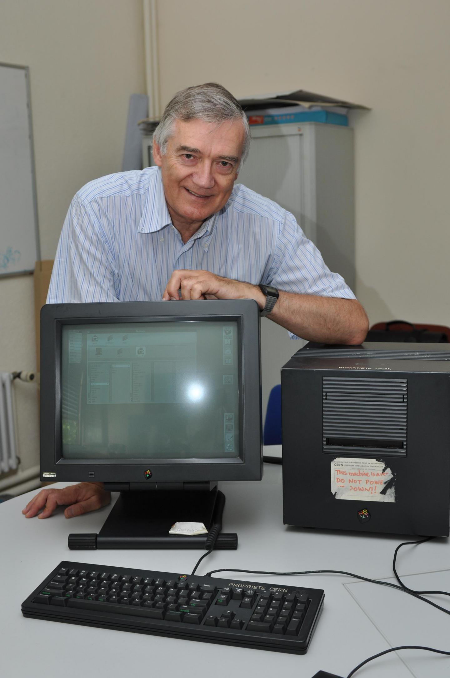
Due to its high price, the NeXTcube was not a commercial success. It mainly ended up at companies or in the hands of researchers. Two of those researchers, Tim Berners-Lee and [Robert Cailliau](https://en.wikipedia.org/wiki/Robert_Cailliau) created the first [`http` server and web browser](https://cds.cern.ch/record/1547556) at CERN on a NeXTcube. Coincidently, [the http software was publicly released exactly 30 years ago](https://web30.web.cern.ch/web-history.html) today. Famously, the cube was also used to develop games like the original Doom and Quake. So yes, the NeXTcube runs Doom.
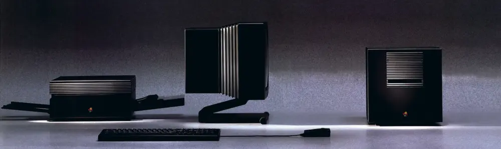
Fig: the NeXTcube's design stood out compared to the contemporary beige box PCs.
Less well known is the fact that the NeXTcube is also one of the first computing devices capable enough for real-time, high-quality interactive music applications. In the mid 1980s this was still a dream at [IRCAM](https://www.ircam.fr/), a French research institute with the aim to *'contribute to the renewal of musical expression through science and technology'*. The bespoke hardware and software systems for music applications from the mid 80s were further developed and commercialised in the early 90s. Together these developments resulted in a commercially available version of the "*IRCAM Musical Workstation (IMW)*", an early, if not the first, off-the-shelf computer for interactive music applications.
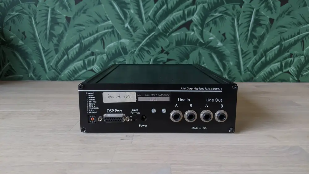
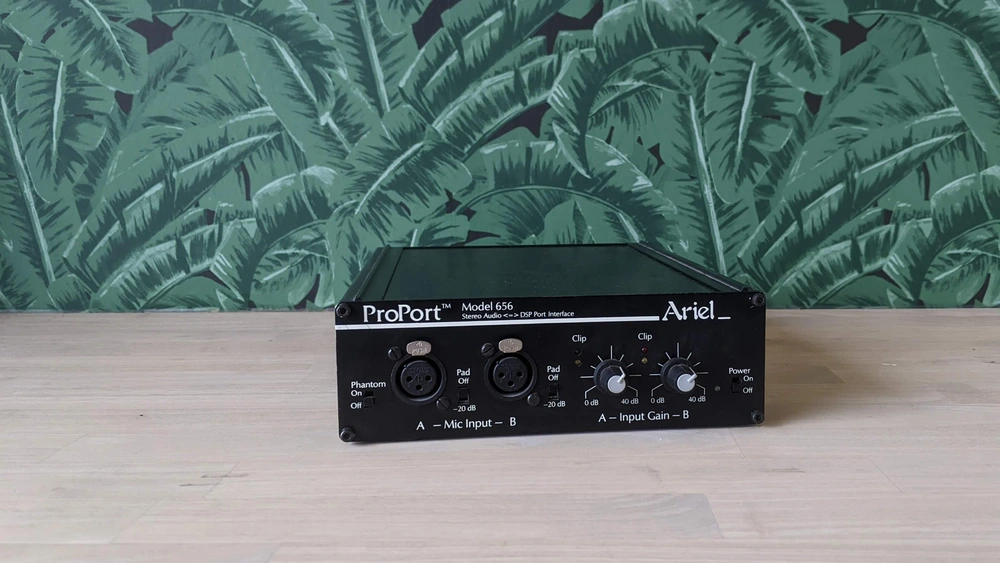
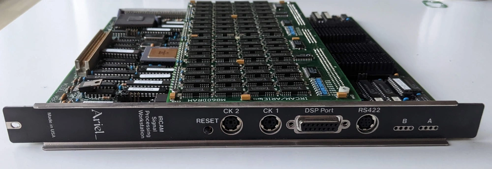
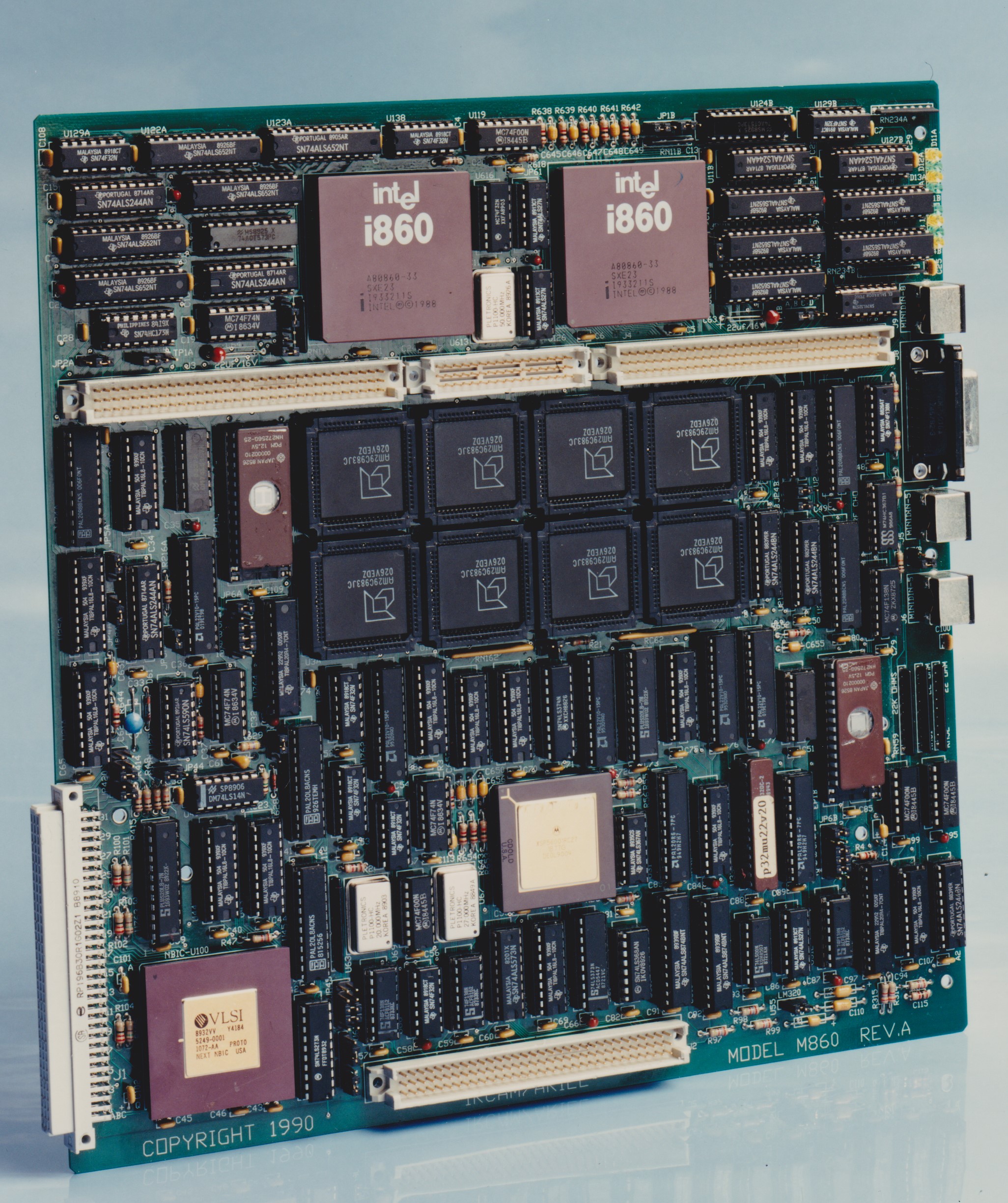
The IRCAM Musical Workstation (IMW), sometimes called the IRCAM Signal Processing Workstation (ISPW), consisted of several hard and software modules working together to enable interactive music applications. An important component was a 'soundcard' which had two beefy 40MHz [i860 intel CPUs](https://en.wikipedia.org/wiki/Intel_i860) for DSP. When installed in the NeXTcube, the soundcard had more computing power than the rest of the computer. This is similar to modern computers where some graphics cards have more raw computing power than the main CPU. The soundcard was developed at IRCAM and commercialized by Ariel inc. under the name "Ariel ProPort".
The IRCAM Ariel DSP coprocessor, soundcard.
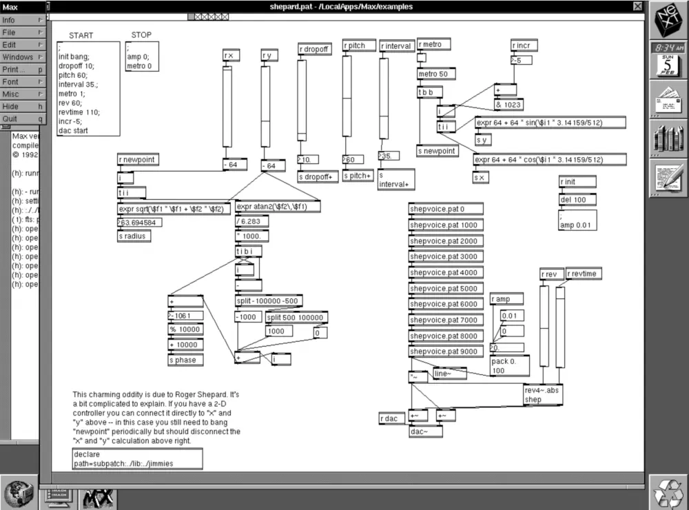
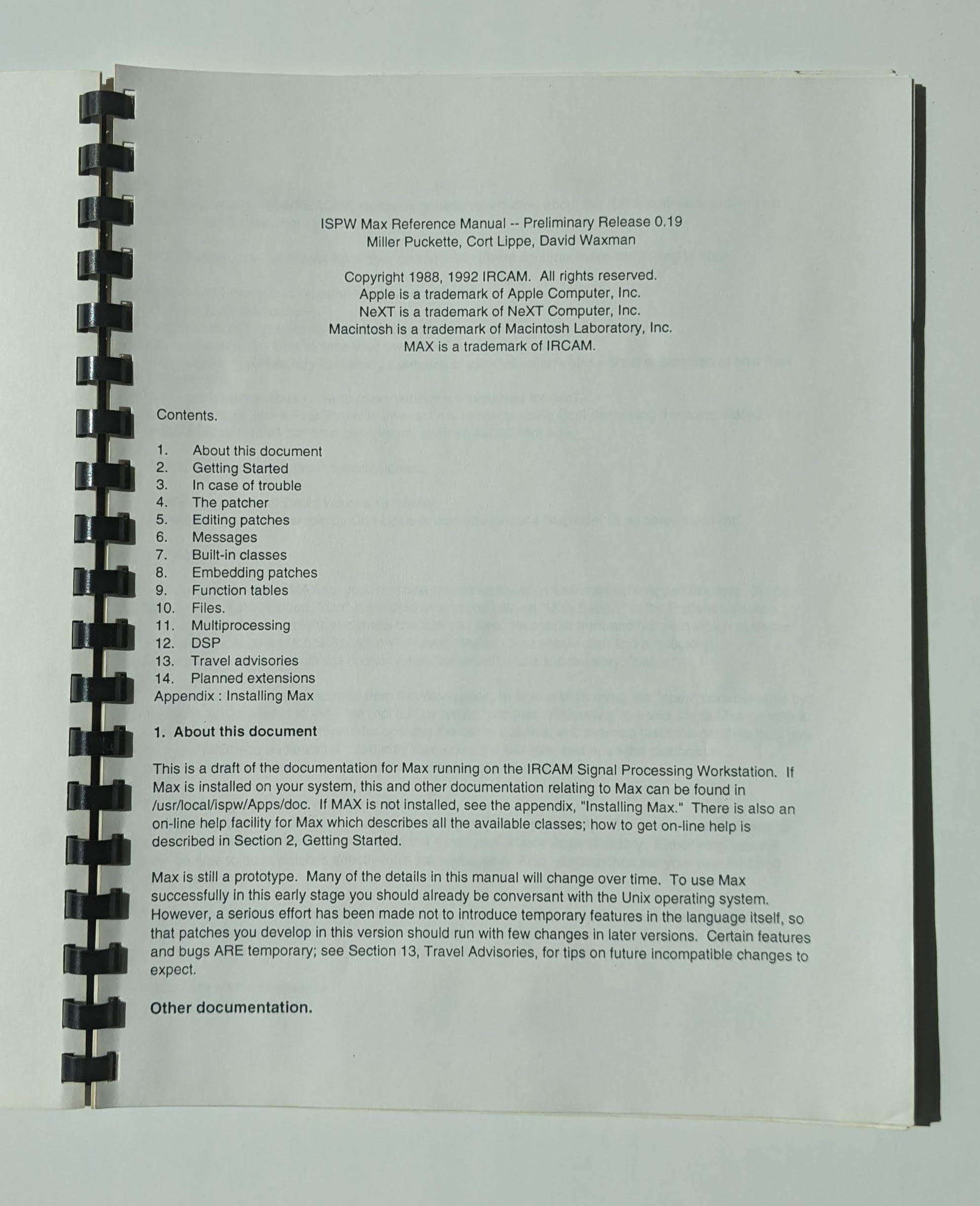
A few software environments were developed at IRCAM which made use of the new hardware. One was Animal, another, was the much more influential MAX. MAX provides a graphical programming environment specific for music applications. Descendants of MAX are still used today, see [Ableton Max for Live](https://www.ableton.com/en/live/max-for-live/) and [Pure Data](https://puredata.info). I consider the *introduction of MAX as a pivotal point in electronic music history*. Up until the introduction of MAX, creating a new electronic music instrument meant bespoke hardware development. With MAX, this is done purely in software. This made electronic sound or instrument design not only faster but also accessible to a much wider audience of composers, artists and thinkerers.
### The NeXTcube at IPEM
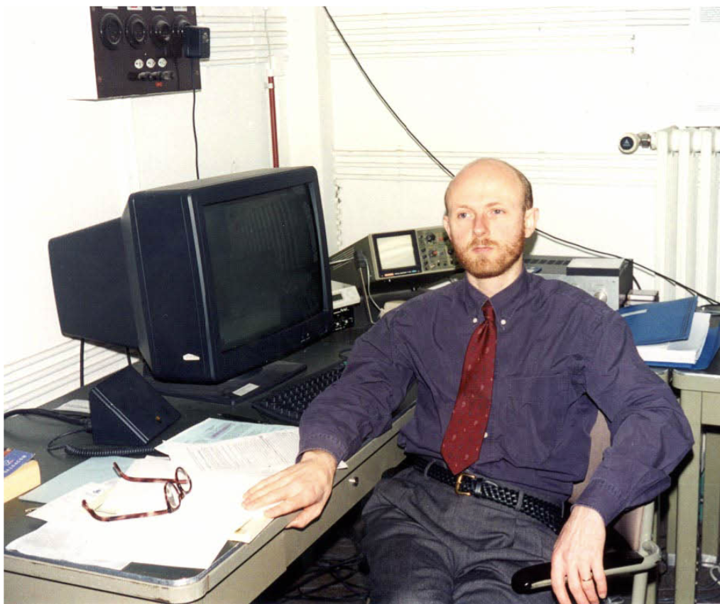
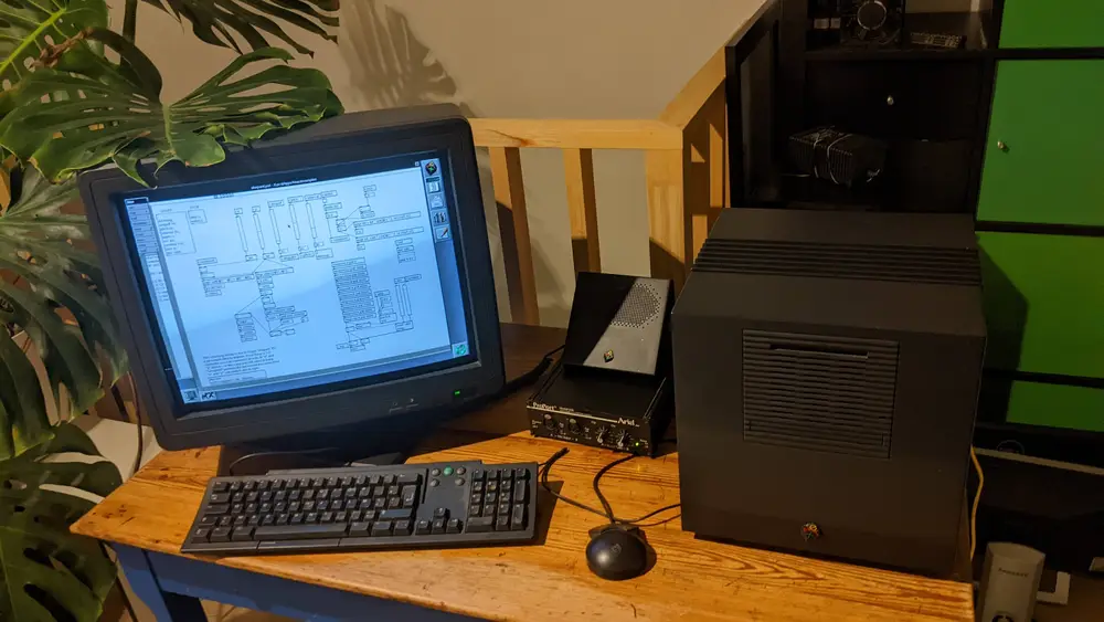
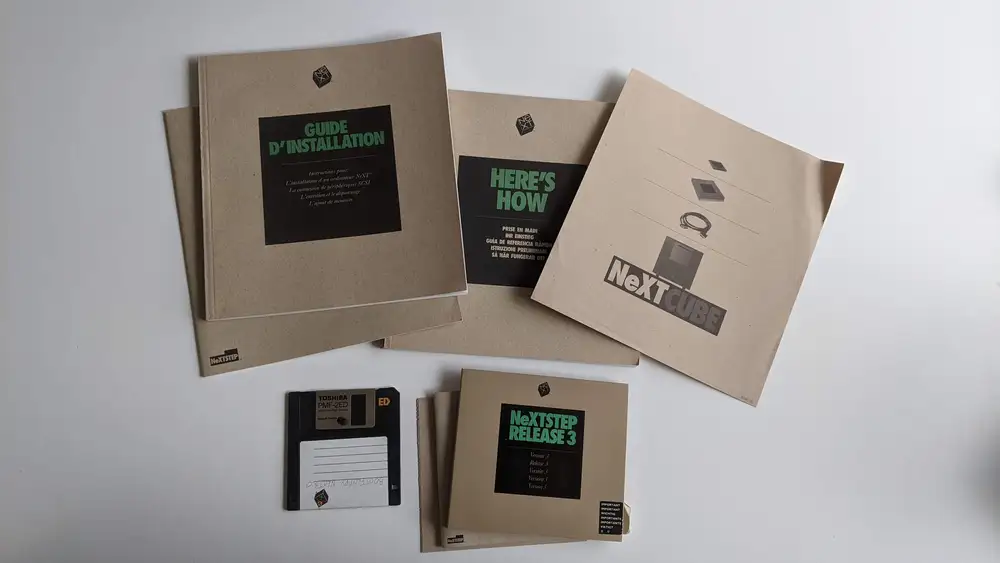
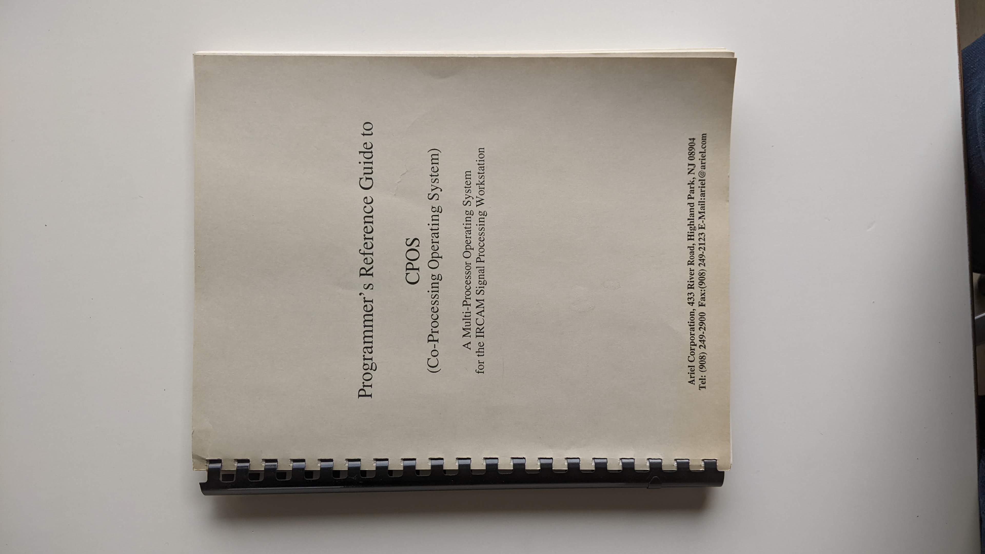
IPEM was an early electronic music production studio embedded at Ghent University, Belgium. Now it is active as a internationally acclaimed [research center for interdisciplinary music research](https://www.ugent.be/lw/kunstwetenschappen/ipem/en). In the early 90s IPEM acquired a [NeXTcube Turbo](https://en.wikipedia.org/wiki/NeXTcube_Turbo) with an internal diskette drive, SCSI hard disk, NextDimension color graphics card and an Ariel ProPort DSP/ISPW module. The cube was preserved well and came with many of the original software, books and manuals. I have been trying to get this machine working and configure it as an "*IRCAM Musical Workstation*".
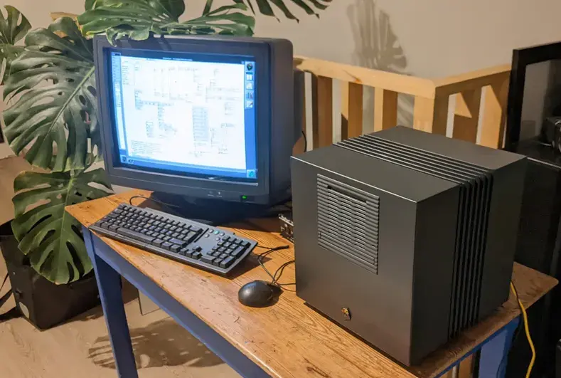
IPEM's NeXTcube with IRCAM Ariel ProPort.
There were a few practical issues: the mouse was broken, the hard drive unreliable and the main system fan loud and full of dust. The mouse had a broken cable which was fixed, the hard drive was replaced by a [SCSI2SD](https://www.scsi2sd.com) setup and the fan was replaced with a new one. On the software side of things, the Internet Archive hosts [NeXTStep 3.3](https://archive.org/details/NeXTSTEP33CISC) which, after many attempts, was installed on the cube. Unfortunately there seemed to be a compatibility issue. The Ariel ProPort kernel module did not work. I started over installed NeXTStep 3.1, with the same result. Finally, I installed NeXTStep 3.0 which was compatible with the kernel module and MAX/FTS!
Vid: Max/FTS with a commercial Ariel soundcard running on a NeXTcube Turbo.
The restoration of the IRCAM Signal Processing Workstation instruments fits in a [university project on living heritage](https://asil.ugent.be/projects/#heritageinstruments) The idea is to get key historic electronic music instruments into the hands of researchers and artists to pull the fading knowledge on these devices back into a living culture of interaction. This idea already resulted in an album: [DEEWEE Sessions vol. 01](https://store.deeweestudio.com/products/deewee-sessions-vol-01). Currently the collection includes a 1960s reverb plate, an EMS Synti 100 analog synthesizer from the 70s, a Yamaha DX7 (80s) and finally the NeXTCube/ISPW represents the early 90s and the departure of physical instruments to immaterial software based systems.
**Acknowledgements & Further reading**
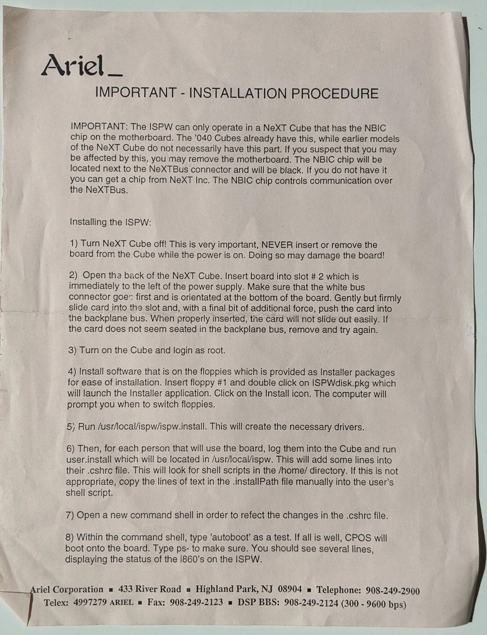
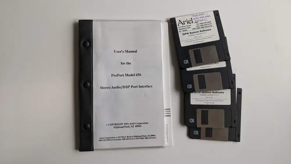
This project was made possible with the support of the Belgian [Music Instrument Museum](https://mim.be) and [IPEM, Ghent University](https://www.ugent.be/lw/kunstwetenschappen/ipem/en). I was fortunate to get assistance by Ivan Schepers and Marc Leman at IPEM but also by the main developers of MAX: [Miller Puckette](http://msp.ucsd.edu/). I would also like to thank Anthony Agnello formerly at Ariel Corp for additional image material and info. I also found the [WinWorld](https://winworldpc.com/product/nextstep/3x) and [NeXTComputers](https://www.nextcomputers.org/NeXTfiles/Images/Rare_NeXT_Hardware/NeXTcube/ISPW/) communities and resources extremely helpful. Below a picture from the [CERN public archives]( https://cds.cern.ch/record/1547556?ln=en) and Ghent University Archive is included. Thanks a lot!
See also the [discussion on this article at Hacker News](https://news.ycombinator.com/item?id=35800380 )\
Lindemann, E., Dechelle, F., Smith, B., & Starkier, M. (1991). [*The Architecture of the IRCAM Musical Workstation*](https://doi.org/10.2307/3680764) - Computer Music Journal, 15(3), 41--49. \
Puckette, M. (1991). [*FTS: A Real-Time Monitor for Multiprocessor Music Synthesis*](https://doi.org/10.2307/3680766). Computer Music Journal, 15(3), 58--67. \
Puckette, M. 1988. [*The Patcher*](http://msp.ucsd.edu/Publications/icmc88.pdf), Proceedings, ICMC. San Francisco: International Computer Music Association, pp. 420-429. \
Puckette, M. 1991. [*Combining Event and Signal Processing in the MAX Graphical Programming Environment.*](http://msp.ucsd.edu/Publications/cmj91-max.ps) Computer Music Journal 15(3): 68-77.\


---
## [An Arduino Trigger Box](https://0110.be/posts/An_Arduino_Trigger_Box.md)
- Published: 2023-03-31T00:00:00Z
- Updated: 2025-11-29T14:20:05Z
- Author: Joren
- ID: 510
- Canonical: https://0110.be/posts/An_Arduino_Trigger_Box
- Tags: [Harde waren](https://0110.be/tags/Harde%20waren.md), [UGent](https://0110.be/tags/UGent.md)
Vid: the trigger box set in recording mode via a button or a MIDI key press.
A while back I have build a trigger box. Such device can be used for various synchronisation tasks. It can be used to synchronise camera's, capture devices and sensors. All compatible devices have a 5V `TTL` input, often a `BNC` connector. For a camera, `TTL` input could control the *shutter time*. For a sensor a `TTL` clock could determine the *sample time* or simply be registered along side an other data stream. The trigger box allows to either pass-through (or block) an incoming `TTL` clock. It also outputs a recording level.
There are two ways to use the trigger box. The first is by operating a *manual switch* to start (and later stop) a recording. When recording, the recording level output is set to 5V and the clock at the `CLOCK IN` is passed through to the `CLOCK OUT` port. The second way to set the recording state is by *`MIDI` over `USB`*. While a `MIDI` key is pressed, the recording state is high, when the key is released the state is low. The `MIDI` key input makes it compatible and controllable from any `DAW`. Both ways are shown in the video.
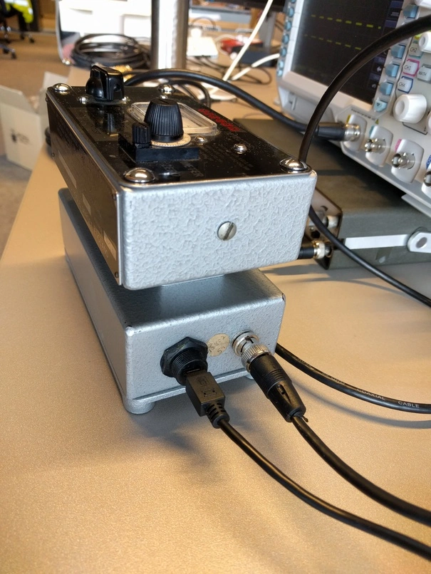
For practical reasons there are two microcontrollers in the device, a Teensy 3.2 and an Arduino. The Arduino is there for its 5V capabilities and is essentially a rather beefy level-shifter. The Teensy is there for the `USB` `MIDI` compatibility and controls everything.
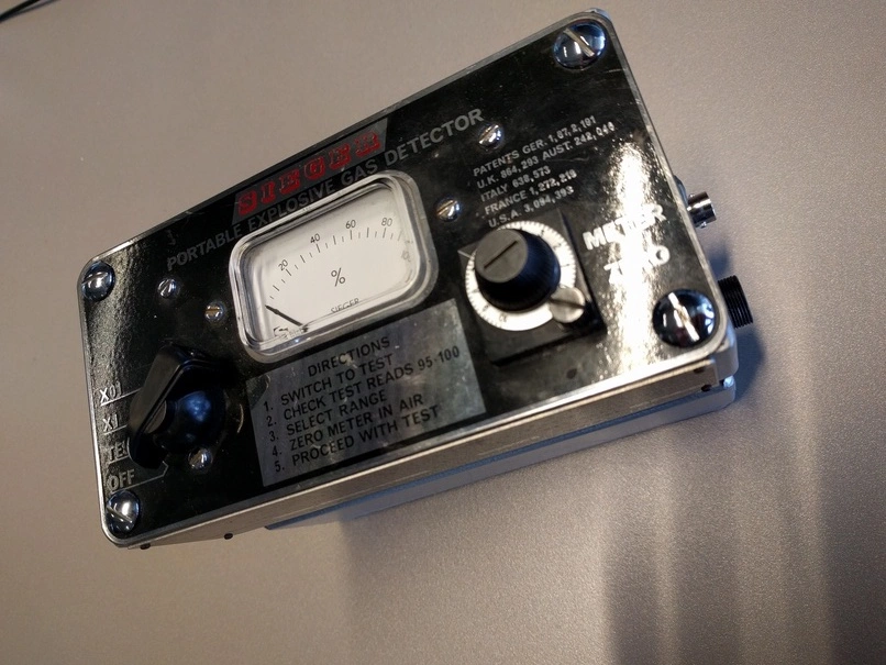
For aesthetic reasons the trigger box has been build into a 1950s '*Sieger portable explosive gas detector*'. I did not feel too bad about gutting the original electronics since a battery leak had destroyed most of it. Also, the late WII era knobs are still unmatched for durability and tactile satisfaction.
The code running on the microcontrollers and some documentation can be found on the [Trigger Box github repository.](https://github.com/ArtScienceLab/ARDUINO_TriggerBox)
---
## [Notifications from an RFduino over Bluetooth LE (4.0) on a Linux machine](https://0110.be/posts/Notifications_from_an_RFduino_over_Bluetooth_LE_%284.0%29_on_a_Linux_machine.md)
- Published: 2015-05-21T00:00:00Z
- Updated: 2025-11-29T20:15:07Z
- Author: Joren
- ID: 433
- Canonical: https://0110.be/posts/Notifications_from_an_RFduino_over_Bluetooth_LE_%284.0%29_on_a_Linux_machine
- Tags: [Code](https://0110.be/tags/Code.md), [Harde waren](https://0110.be/tags/Harde%20waren.md), [IPEM](https://0110.be/tags/IPEM.md), [UGent](https://0110.be/tags/UGent.md)
This post describes how to get notifications from a Bluetooth LE (Low Energy) or Bluetooth v4.0 device on a Linux machine. Since it took me a while to get it going it is perhaps of interest to others.
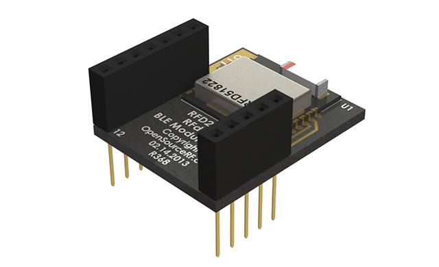
The hardware I used is an [RFduino](http://www.rfduino.com/) board and a Belikin mini Bluethooth v4.0 adapter. The RFduino was programmed to wait for an event with `RFduino_pinWake(pni, HIGH)`. When the pin is `HIGH` a count is incremented and this number is send to any device that is listening. In my case a Linux machine. The code is essentially the same as the button example included in the RDduino software distribution.
To install the Bluetooth stack on Debian the following command is executed `sudo apt-get install bluetooth bluez bluez-utils bluez-firmware`. A blog post describes more about the [Bluetooth tools](http://mike.saunby.net/2013/04/raspberry-pi-and-ti-cc2541-sensortag.html). Some other interesting reads are [Get started with Bluetooth Low Energy](http://www.jaredwolff.com/blog/get-started-with-bluetooth-low-energy/) and this [stackoverflow question](https://stackoverflow.com/questions/15657007/bluetooth-low-energy-listening-for-notifications-indications-in-linux). Once the stack is installed correctly the `lescan` utility should give an output like this:
````
$ sudo hcitool lescan
LE Scan ...
DC:87:CC:18:14:A5 RFduino
DC:87:CC:18:14:A5 (unknown)
````
Bluetooth LE works with the Generic Attribute Profile (GATT). A Bluetooth LE device can provide services by combining characteristics. These characteristics are the way to communicate with the device. Some characteristics are writable and are able to send notifications. To receive notifications one such characteristic (referred to with a hex handle) needs to be written. Write 0100 to get notifications, 0200 for indications (indications are notifications that are acknowledged), 0300 for both, or 0000 for nothing (default). With this in mind, the following command enables listening for notifications:
````
gatttool ---device=DC:87:CC:18:14:A5 ---char-write-req ---handle=0x000f ---value=0300 ---listen
````
With those commands working, the process can be automated with "a Ruby script to get Bluetooth LE notifications":\[bluetooth_notifications.rb\]. The script essentially calls `gatttool` with the correct parameters and parses and reacts to its output. To make it work `lescan` needs to be called before starting the script:
````
\$ sudo hcitool lescan && ruby bluetooth_notifications.rb
LE Scan ...
DC:87:CC:18:14:A5 RFduino
DC:87:CC:18:14:A5 (unknown)
Characteristic value was written successfully
Notification handle = 0x000e value: 41 decimal value: 65
Notification handle = 0x000e value: 42 decimal value: 66
Notification handle = 0x000e value: 43 decimal value: 67
Notification handle = 0x000e value: 44 decimal value: 68
Notification handle = 0x000e value: 45 decimal value: 69
Notification handle = 0x000e value: 46 decimal value: 70
````
- [rfd22102.jpg](https://0110.be/files/attachments/433/rfd22102.jpg)
- [bluetooth\_notifications.rb](https://0110.be/files/attachments/433/bluetooth_notifications.rb)
---
## [Power Socket Control with Arduino](https://0110.be/posts/Power_Socket_Control_with_Arduino.md)
- Published: 2014-01-06T00:00:00Z
- Updated: 2014-08-21T21:28:40Z
- Author: Joren
- ID: 414
- Canonical: https://0110.be/posts/Power_Socket_Control_with_Arduino
- Tags: [Code](https://0110.be/tags/Code.md), [Hackerspace Ghent](https://0110.be/tags/Hackerspace%20Ghent.md), [Harde waren](https://0110.be/tags/Harde%20waren.md), [Projecten](https://0110.be/tags/Projecten.md)
This post contains some info on how do some basic home automation: it shows how cheap remote controlled power sockets can be managed using a computer. The aim is to power on or power off lights, a stereo or other devices remotely from a command shell.
The solution here uses an Arduino connected to a 433.33MHz transmitter. Via a Ruby script installed on the computer a command is send over serial to the Arduino. Subsequently the Arduino sends the command over the air to the power socket(s). If all goes well the power socket reacts by switching the connecting device on or off.
In the video below the process is shown. The command line interface controls the light via the Arduino. It should show the general idea.



 This post describes how to get notifications from a Bluetooth LE (Low Energy) or Bluetooth v4.0 device on a Linux machine. Since it took me a while to get it going it is perhaps of interest to others.
The hardware I used is an [RFduino](http://www.rfduino.com/) board and a Belikin mini Bluethooth v4.0 adapter. The RFduino was programmed to wait for an event with `RFduino_pinWake(pni, HIGH)`. When the pin is `HIGH` a count is incremented and this number is send to any device that is listening. In my case a Linux machine. The code is essentially the same as the button example included in the RDduino software distribution.
To install the Bluetooth stack on Debian the following command is executed `sudo apt-get install bluetooth bluez bluez-utils bluez-firmware`. A blog post describes more about the [Bluetooth tools](http://mike.saunby.net/2013/04/raspberry-pi-and-ti-cc2541-sensortag.html). Some other interesting reads are [Get started with Bluetooth Low Energy](http://www.jaredwolff.com/blog/get-started-with-bluetooth-low-energy/) and this [stackoverflow question](https://stackoverflow.com/questions/15657007/bluetooth-low-energy-listening-for-notifications-indications-in-linux). Once the stack is installed correctly the `lescan` utility should give an output like this:
````
$ sudo hcitool lescan
LE Scan ...
DC:87:CC:18:14:A5 RFduino
DC:87:CC:18:14:A5 (unknown)
````
Bluetooth LE works with the Generic Attribute Profile (GATT). A Bluetooth LE device can provide services by combining characteristics. These characteristics are the way to communicate with the device. Some characteristics are writable and are able to send notifications. To receive notifications one such characteristic (referred to with a hex handle) needs to be written. Write 0100 to get notifications, 0200 for indications (indications are notifications that are acknowledged), 0300 for both, or 0000 for nothing (default). With this in mind, the following command enables listening for notifications:
````
gatttool ---device=DC:87:CC:18:14:A5 ---char-write-req ---handle=0x000f ---value=0300 ---listen
````
With those commands working, the process can be automated with "a Ruby script to get Bluetooth LE notifications":\[bluetooth_notifications.rb\]. The script essentially calls `gatttool` with the correct parameters and parses and reacts to its output. To make it work `lescan` needs to be called before starting the script:
````
\$ sudo hcitool lescan && ruby bluetooth_notifications.rb
LE Scan ...
DC:87:CC:18:14:A5 RFduino
DC:87:CC:18:14:A5 (unknown)
Characteristic value was written successfully
Notification handle = 0x000e value: 41 decimal value: 65
Notification handle = 0x000e value: 42 decimal value: 66
Notification handle = 0x000e value: 43 decimal value: 67
Notification handle = 0x000e value: 44 decimal value: 68
Notification handle = 0x000e value: 45 decimal value: 69
Notification handle = 0x000e value: 46 decimal value: 70
````
- [rfd22102.jpg](https://0110.be/files/attachments/433/rfd22102.jpg)
- [bluetooth\_notifications.rb](https://0110.be/files/attachments/433/bluetooth_notifications.rb)
---
## [Power Socket Control with Arduino](https://0110.be/posts/Power_Socket_Control_with_Arduino.md)
- Published: 2014-01-06T00:00:00Z
- Updated: 2014-08-21T21:28:40Z
- Author: Joren
- ID: 414
- Canonical: https://0110.be/posts/Power_Socket_Control_with_Arduino
- Tags: [Code](https://0110.be/tags/Code.md), [Hackerspace Ghent](https://0110.be/tags/Hackerspace%20Ghent.md), [Harde waren](https://0110.be/tags/Harde%20waren.md), [Projecten](https://0110.be/tags/Projecten.md)
This post contains some info on how do some basic home automation: it shows how cheap remote controlled power sockets can be managed using a computer. The aim is to power on or power off lights, a stereo or other devices remotely from a command shell.
The solution here uses an Arduino connected to a 433.33MHz transmitter. Via a Ruby script installed on the computer a command is send over serial to the Arduino. Subsequently the Arduino sends the command over the air to the power socket(s). If all goes well the power socket reacts by switching the connecting device on or off.
In the video below the process is shown. The command line interface controls the light via the Arduino. It should show the general idea.
This post describes how to get notifications from a Bluetooth LE (Low Energy) or Bluetooth v4.0 device on a Linux machine. Since it took me a while to get it going it is perhaps of interest to others.
The hardware I used is an [RFduino](http://www.rfduino.com/) board and a Belikin mini Bluethooth v4.0 adapter. The RFduino was programmed to wait for an event with `RFduino_pinWake(pni, HIGH)`. When the pin is `HIGH` a count is incremented and this number is send to any device that is listening. In my case a Linux machine. The code is essentially the same as the button example included in the RDduino software distribution.
To install the Bluetooth stack on Debian the following command is executed `sudo apt-get install bluetooth bluez bluez-utils bluez-firmware`. A blog post describes more about the [Bluetooth tools](http://mike.saunby.net/2013/04/raspberry-pi-and-ti-cc2541-sensortag.html). Some other interesting reads are [Get started with Bluetooth Low Energy](http://www.jaredwolff.com/blog/get-started-with-bluetooth-low-energy/) and this [stackoverflow question](https://stackoverflow.com/questions/15657007/bluetooth-low-energy-listening-for-notifications-indications-in-linux). Once the stack is installed correctly the `lescan` utility should give an output like this:
````
$ sudo hcitool lescan
LE Scan ...
DC:87:CC:18:14:A5 RFduino
DC:87:CC:18:14:A5 (unknown)
````
Bluetooth LE works with the Generic Attribute Profile (GATT). A Bluetooth LE device can provide services by combining characteristics. These characteristics are the way to communicate with the device. Some characteristics are writable and are able to send notifications. To receive notifications one such characteristic (referred to with a hex handle) needs to be written. Write 0100 to get notifications, 0200 for indications (indications are notifications that are acknowledged), 0300 for both, or 0000 for nothing (default). With this in mind, the following command enables listening for notifications:
````
gatttool ---device=DC:87:CC:18:14:A5 ---char-write-req ---handle=0x000f ---value=0300 ---listen
````
With those commands working, the process can be automated with "a Ruby script to get Bluetooth LE notifications":\[bluetooth_notifications.rb\]. The script essentially calls `gatttool` with the correct parameters and parses and reacts to its output. To make it work `lescan` needs to be called before starting the script:
````
\$ sudo hcitool lescan && ruby bluetooth_notifications.rb
LE Scan ...
DC:87:CC:18:14:A5 RFduino
DC:87:CC:18:14:A5 (unknown)
Characteristic value was written successfully
Notification handle = 0x000e value: 41 decimal value: 65
Notification handle = 0x000e value: 42 decimal value: 66
Notification handle = 0x000e value: 43 decimal value: 67
Notification handle = 0x000e value: 44 decimal value: 68
Notification handle = 0x000e value: 45 decimal value: 69
Notification handle = 0x000e value: 46 decimal value: 70
````
- [rfd22102.jpg](https://0110.be/files/attachments/433/rfd22102.jpg)
- [bluetooth\_notifications.rb](https://0110.be/files/attachments/433/bluetooth_notifications.rb)
---
## [Power Socket Control with Arduino](https://0110.be/posts/Power_Socket_Control_with_Arduino.md)
- Published: 2014-01-06T00:00:00Z
- Updated: 2014-08-21T21:28:40Z
- Author: Joren
- ID: 414
- Canonical: https://0110.be/posts/Power_Socket_Control_with_Arduino
- Tags: [Code](https://0110.be/tags/Code.md), [Hackerspace Ghent](https://0110.be/tags/Hackerspace%20Ghent.md), [Harde waren](https://0110.be/tags/Harde%20waren.md), [Projecten](https://0110.be/tags/Projecten.md)
This post contains some info on how do some basic home automation: it shows how cheap remote controlled power sockets can be managed using a computer. The aim is to power on or power off lights, a stereo or other devices remotely from a command shell.
The solution here uses an Arduino connected to a 433.33MHz transmitter. Via a Ruby script installed on the computer a command is send over serial to the Arduino. Subsequently the Arduino sends the command over the air to the power socket(s). If all goes well the power socket reacts by switching the connecting device on or off.
In the video below the process is shown. The command line interface controls the light via the Arduino. It should show the general idea.
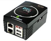 \
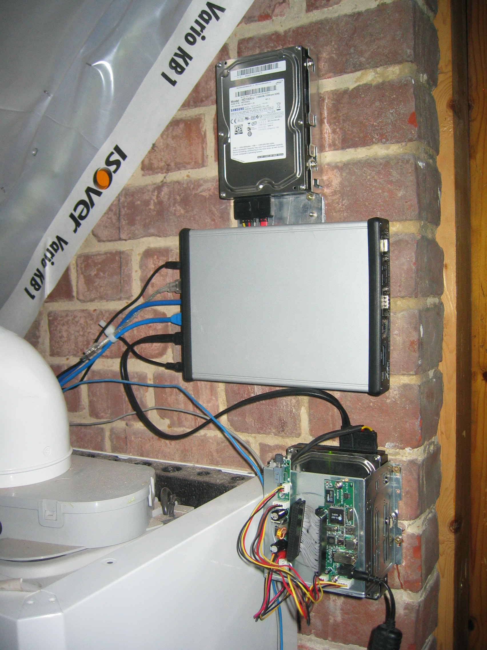
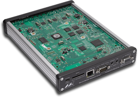
This blog post comments on using the Marvell OpenRD SoC(System on a Chip) as a low power multipurpose home server.
### The Hardware
The specifications of the [OpenRD SoC](http://open-rd.org) are very similar to the better known [SheevaPlug](http://en.wikipedia.org/wiki/SheevaPlug) devices, so it has 512MB DDR2 RAM, an 1.2GHz ARM processor and 512MB internal flash. To be more precise the OpenRD SoC is essentially a SheevaPlug in a different form factor. The main advantage of this form factor is the number of available connections: 7xUSB, SATA, eSATA, 2xGb Ethernet, VGA, Audio, ... which make the device a lot more extendable and practical as a mulitpurpose home server.
### The Software
Thanks to the work of [Dr. Martin Michlmayr](http://www.cyrius.com) there is a Debian port for the Kirkwood platform readily available. He even wrote a tutorial on [how to install Debian on a SheevaPlug](http://www.cyrius.com/debian/kirkwood/sheevaplug/install.html). Installing Debian on an OpenRD is exactly the same except for one important detail: the `arcNumber` variable.
Once Debian is installed you can `apt-get` or `aptitude` almost all the software you are used to: webserver, samba, ruby, ...
### The Alternatives
- [Sheevaplug](http://en.wikipedia.org/wiki/SheevaPlug)
- [Beagle Board](http://beagleboard.org) or other [OMAP3 SoC's](http://processors.wiki.ti.com/index.php?title=OMAP3_Boards). The IGEPv2 e.g. has wireless and wired network connections.
- [Alix system Boards](http://www.pcengines.ch/alix.htm) are mostly x86 based.
- [NSLU2](http://en.wikipedia.org/wiki/NSLU2) An ARM platform.
---
## [Touchatag RFID reader and Ubuntu Linux](https://0110.be/posts/Touchatag_RFID_reader_and_Ubuntu_Linux.md)
- Published: 2009-10-05T00:00:00Z
- Updated: 2013-12-05T18:19:15Z
- Author: Joren
- ID: 56
- Canonical: https://0110.be/posts/Touchatag_RFID_reader_and_Ubuntu_Linux
- Tags: [0110.be](https://0110.be/tags/0110.be.md), [Code](https://0110.be/tags/Code.md), [Harde waren](https://0110.be/tags/Harde%20waren.md), [Projecten](https://0110.be/tags/Projecten.md)

This blog post is about how to use the [Touchatag](http://www.touchatag.com) RFID reader hardware on Ubuntu Linux without using the Touchatag web service.
An RFID reader with tags can used to fire events. With a bit of scripting the events can be handled to do practically any task.
Normally a Touchatag reader is used together with the [Touchatag web service](http://www.touchatag.com/developer/tools/advanced-http-application) but for some RFID applications the web service is just not practical. E.g. for embedded Linux devices without an Internet connection. In this tutorial I wil document how I got the Touchatag hardware working under Ubuntu Linux.
To follow this tutorial you will need:
- Touchatag hardware: the USB reader and some tags
- A Ubuntu Linux computer (I tested 9.10 Karmic Koala and 8.04 )
- SVN to download source code from a repository
The touchatag USB reader works at 13.56MHz (High Frequency RFID) and has a readout distance of about 4 cm (1.5 inch) when used with the touchatag RFID tags. Internally it uses an ACS ACR122U reader with a SAM card. A Linux driver is readily available so when you plug it in `lsusb` you should get something like this:
\`\`\`ruby\
lsusb
Bus 007 Device 001: ID 1d6b:0001 Linux Foundation 1.1 root hub\
Bus 005 Device 004: ID 072e:90dd Advanced Card Systems, Ltd\
\`\`\`
lsusb recognizes the device incorrectly but that's [not a problem](http://code.google.com/p/tageventor/wiki/SupportedReadersAndTags). To read RFID-tags and respond to events additional software is needed: [tagEventor](http://code.google.com/p/tageventor/) is a software library that does just that. It can be downloaded using an svn command:
\`\`\`ruby\
svn export http://tageventor.googlecode.com svn/trunk/ tageventor\
\`\`\`
To compile tagEventor a couple of other software packages or header files should be available on your system. Te [tagEventor software dependencies](http://code.google.com/p/tageventor/wiki/SoftwareDependencies) are described on the [tagEventor wiki](http://code.google.com/p/tageventor/w/list). On Ubuntu (and possibly other Debian based distro's the installation is simple:
\`\`\`ruby\
sudo aptitude install build-essential libpcsclite-dev build-essential pcscd libccid\
#if you need gnome support\
#sudo aptitude install libgtk2.0-dev\
\`\`\`
\
This blog post comments on using the Marvell OpenRD SoC(System on a Chip) as a low power multipurpose home server.
### The Hardware
The specifications of the [OpenRD SoC](http://open-rd.org) are very similar to the better known [SheevaPlug](http://en.wikipedia.org/wiki/SheevaPlug) devices, so it has 512MB DDR2 RAM, an 1.2GHz ARM processor and 512MB internal flash. To be more precise the OpenRD SoC is essentially a SheevaPlug in a different form factor. The main advantage of this form factor is the number of available connections: 7xUSB, SATA, eSATA, 2xGb Ethernet, VGA, Audio, ... which make the device a lot more extendable and practical as a mulitpurpose home server.
### The Software
Thanks to the work of [Dr. Martin Michlmayr](http://www.cyrius.com) there is a Debian port for the Kirkwood platform readily available. He even wrote a tutorial on [how to install Debian on a SheevaPlug](http://www.cyrius.com/debian/kirkwood/sheevaplug/install.html). Installing Debian on an OpenRD is exactly the same except for one important detail: the `arcNumber` variable.
Once Debian is installed you can `apt-get` or `aptitude` almost all the software you are used to: webserver, samba, ruby, ...
### The Alternatives
- [Sheevaplug](http://en.wikipedia.org/wiki/SheevaPlug)
- [Beagle Board](http://beagleboard.org) or other [OMAP3 SoC's](http://processors.wiki.ti.com/index.php?title=OMAP3_Boards). The IGEPv2 e.g. has wireless and wired network connections.
- [Alix system Boards](http://www.pcengines.ch/alix.htm) are mostly x86 based.
- [NSLU2](http://en.wikipedia.org/wiki/NSLU2) An ARM platform.


---
## [Touchatag RFID reader and Ubuntu Linux](https://0110.be/posts/Touchatag_RFID_reader_and_Ubuntu_Linux.md)
- Published: 2009-10-05T00:00:00Z
- Updated: 2013-12-05T18:19:15Z
- Author: Joren
- ID: 56
- Canonical: https://0110.be/posts/Touchatag_RFID_reader_and_Ubuntu_Linux
- Tags: [0110.be](https://0110.be/tags/0110.be.md), [Code](https://0110.be/tags/Code.md), [Harde waren](https://0110.be/tags/Harde%20waren.md), [Projecten](https://0110.be/tags/Projecten.md)

This blog post is about how to use the [Touchatag](http://www.touchatag.com) RFID reader hardware on Ubuntu Linux without using the Touchatag web service.
An RFID reader with tags can used to fire events. With a bit of scripting the events can be handled to do practically any task.
Normally a Touchatag reader is used together with the [Touchatag web service](http://www.touchatag.com/developer/tools/advanced-http-application) but for some RFID applications the web service is just not practical. E.g. for embedded Linux devices without an Internet connection. In this tutorial I wil document how I got the Touchatag hardware working under Ubuntu Linux.
To follow this tutorial you will need:
- Touchatag hardware: the USB reader and some tags
- A Ubuntu Linux computer (I tested 9.10 Karmic Koala and 8.04 )
- SVN to download source code from a repository
The touchatag USB reader works at 13.56MHz (High Frequency RFID) and has a readout distance of about 4 cm (1.5 inch) when used with the touchatag RFID tags. Internally it uses an ACS ACR122U reader with a SAM card. A Linux driver is readily available so when you plug it in `lsusb` you should get something like this:
\`\`\`ruby\
lsusb
Bus 007 Device 001: ID 1d6b:0001 Linux Foundation 1.1 root hub\
Bus 005 Device 004: ID 072e:90dd Advanced Card Systems, Ltd\
\`\`\`
lsusb recognizes the device incorrectly but that's [not a problem](http://code.google.com/p/tageventor/wiki/SupportedReadersAndTags). To read RFID-tags and respond to events additional software is needed: [tagEventor](http://code.google.com/p/tageventor/) is a software library that does just that. It can be downloaded using an svn command:
\`\`\`ruby\
svn export http://tageventor.googlecode.com svn/trunk/ tageventor\
\`\`\`
To compile tagEventor a couple of other software packages or header files should be available on your system. Te [tagEventor software dependencies](http://code.google.com/p/tageventor/wiki/SoftwareDependencies) are described on the [tagEventor wiki](http://code.google.com/p/tageventor/w/list). On Ubuntu (and possibly other Debian based distro's the installation is simple:
\`\`\`ruby\
sudo aptitude install build-essential libpcsclite-dev build-essential pcscd libccid\
#if you need gnome support\
#sudo aptitude install libgtk2.0-dev\
\`\`\`