~ Power Socket Control with Arduino
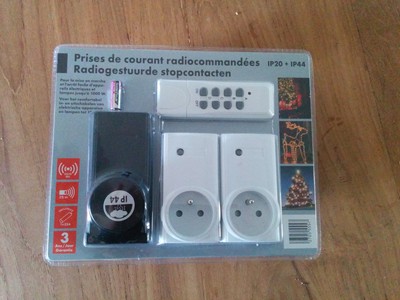
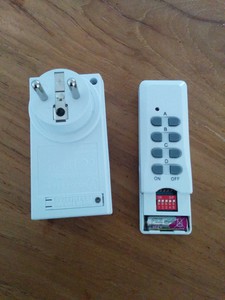
» By Joren on Monday 06 January 2014This post contains some info on how do some basic home automation: it shows how cheap remote controlled power sockets can be managed using a computer. The aim is to power on or power off lights, a stereo or other devices remotely from a command shell.
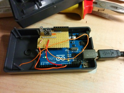
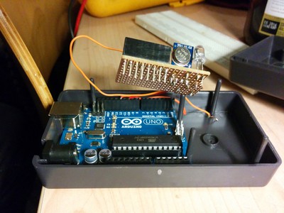
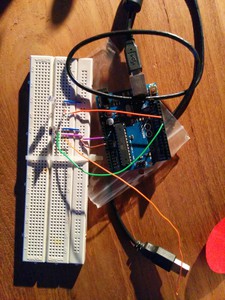
The solution here uses an Arduino connected to a 433.33MHz transmitter. Via a Ruby script installed on the computer a command is send over serial to the Arduino. Subsequently the Arduino sends the command over the air to the power socket(s). If all goes well the power socket reacts by switching the connecting device on or off.
In the video below the process is shown. The command line interface controls the light via the Arduino. It should show the general idea.
The following Ruby script simply sends the binary control codes to the Arduino. For this type of power socket the code consist of a five bit group code and five bit device code. The Arduino is connected to /dev/tty.usbmodem411.
```ruby\ require ‘rubygems’\ require ‘serialport’
group = “11111”;
lamp = “01000” #B\ kerstboom = “00100” #C\ stereo = “00010” #D
port = “/dev/tty.usbmodem411”\ baud_rate = 9600\ data_bits = 8\ stop_bits = 1\ parity = SerialPort::NONE
command = ARGV[1] == “on”
device_string = ARGV[0]\ device = if device_string "kerstboom" kerstboom elsif device_string “lamp”\ lamp\ elsif device_string == “stereo”\ stereo\ end
def send(sp,group,device,deviceOn)\ command = deviceOn ? “1” : “0”\ command.each_char{|c| sp.write©}\ group.each_char{|c| sp.write©}\ device.each_char{|c| sp.write©}\ sp.flush\ read_response sp\ read_response sp\ end
def read_response(sp)\ response = sp.readline\ puts response.chomp\ end
SerialPort.open(port, baud_rate, data_bits, stop_bits, parity) do |sp|\ read_response sp\ send(sp,group,device,command)\ end\ ```
The code below is the complete Arduino sketch. It uses the RCSwich library, which makes the implementation very simple. Essentially it waits for a complete command and transmits it through the connected transmitter. The transmitter connected is a tx433n
```ruby\ #include <RCSwitch.h>
RCSwitch mySwitch = RCSwitch();
char command[12];//2x5 for device and group + command\ int index = 0;\ char currentChar = –1;
//the led pin in use\ int ledPin = 12;
void setup() {\ //start the serial communication\ Serial.begin(9600);\ // 433MHZ Transmitter is connected to Arduino Pin #10\ mySwitch.enableTransmit(10);\ //Led connected to led pin\ pinMode(ledPin, OUTPUT);\ Serial.println(“Started the power command center! Mwoehahaha!”);\ }
void readCommand(){\ //read a command\ while (Serial.available() > 0){\ if(index < 11){\ currentChar = Serial.read(); // Read a character\ command[index] = currentChar; // Store it\ index; // Increment where to write next\ command[index] = ‘\0’; // append termination char\ }\ }\ }
void loop() {\ //read a command\ readCommand();\ //if a command is complete\ if(index == 11){\ Serial.print(“Recieved command: “);\ Serial.println(command);\ char operation = command[0];\ char* group = &command[1];\ //group is 5 bits, as is device\ char* device = &command[6];
//execute the operation\ doSwitch(operation,group,device);\ //reset the index to read a new command\ index=0;\ }\ }
void doSwitch(char operation, char* group, char* device){\ digitalWrite(ledPin, HIGH);\ if(operation == ‘1’){\ mySwitch.switchOn(group, device);\ Serial.print(“Switched on device “);\ } else {\ mySwitch.switchOff(group, device);\ Serial.print(“Switched off device “);\ }\ Serial.println(device);\ digitalWrite(ledPin, LOW);\ }\ ```

