~ An Arduino Trigger Box
» By Joren on Friday 31 March 2023Vid: the trigger box set in recording mode via a button or a MIDI key press.
A while back I have build a trigger box. Such device can be used for various synchronisation tasks. It can be used to synchronise camera’s, capture devices and sensors. All compatible devices have a 5V TTL input, often a BNC connector. For a camera, TTL input could control the shutter time. For a sensor a TTL clock could determine the sample time or simply be registered along side an other data stream. The trigger box allows to either pass-through (or block) an incoming TTL clock. It also outputs a recording level.
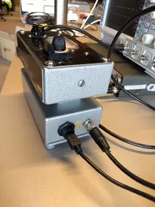
There are two ways to use the trigger box. The first is by operating a manual switch to start (and later stop) a recording. When recording, the recording level output is set to 5V and the clock at the CLOCK IN is passed through to the CLOCK OUT port. The second way to set the recording state is by MIDI over USB. While a MIDI key is pressed, the recording state is high, when the key is released the state is low. The MIDI key input makes it compatible and controllable from any DAW. Both ways are shown in the video.
For practical reasons there are two microcontrollers in the device, a Teensy 3.2 and an Arduino. The Arduino is there for its 5V capabilities and is essentially a rather beefy level-shifter. The Teensy is there for the USB MIDI compatibility and controls everything.
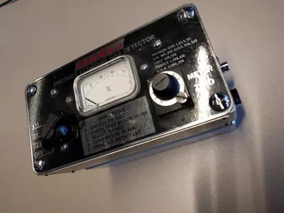
For aesthetic reasons the trigger box has been build into a 1950s ‘Sieger portable explosive gas detector’. I did not feel too bad about gutting the original electronics since a battery leak had destroyed most of it. Also, the late WII era knobs are still unmatched for durability and tactile satisfaction.
The code running on the microcontrollers and some documentation can be found on the Trigger Box github repository.


